
Building 3D-Printable CAD with AI: From Ruler Photos to Parametric Assemblies
How a zip-tied 40 mm fan on a MikroTik switch led us to build a blueprint-first, step-by-step AI CAD skill suite using FigCraft, CadCraft, SolidCraft, and FreeCAD.
Note
Includes our full AI CAD Skill & Agent Pack (download .zip) so you can try this workflow on your own projects.
How it started: A MikroTik switch, a 40 mm Noctua fan, and zip ties
This entire project started by looking at a piece of hardware on my desk that annoyed me. I have a little MikroTik 5-port 10GbE switch that runs hot on the SFP+ cages, and I had a 12V 40 mm Noctua fan strapped to the top of it with zip ties. Looking at those zip ties made me wonder: could I get AI to help me build a clean, simple 3D-printed fan holder fast?
My first pass used headless FreeCAD. Having an AI generate Python scripts for FreeCAD worked well enough to design a clip-on bracket that sits over the 5-port switch and holds the 40 mm Noctua fan right over the SFP+ ports. However, writing raw Python scripts in the dark was brittle. Whenever a dimension shifted by a few millimeters, edge and face indices changed, fillets broke, and the script had to be rewritten from scratch.
Shortly after that first print, the open-source Craft suite of apps launched, including FigCraft, CADCraft, ArtCraft Launcher, and SolidCraft. Because those apps were built in Rust from the ground up with Model Context Protocol, or MCP, and AI-first geometry interfaces, the AI no longer had to guess at monolithic scripts. Instead, an agent could issue structured tool calls like parameters.add, sketch.create, and solid.extrude directly to 2D drafting and 3D parametric CAD engines, inspecting the geometry after every single step.
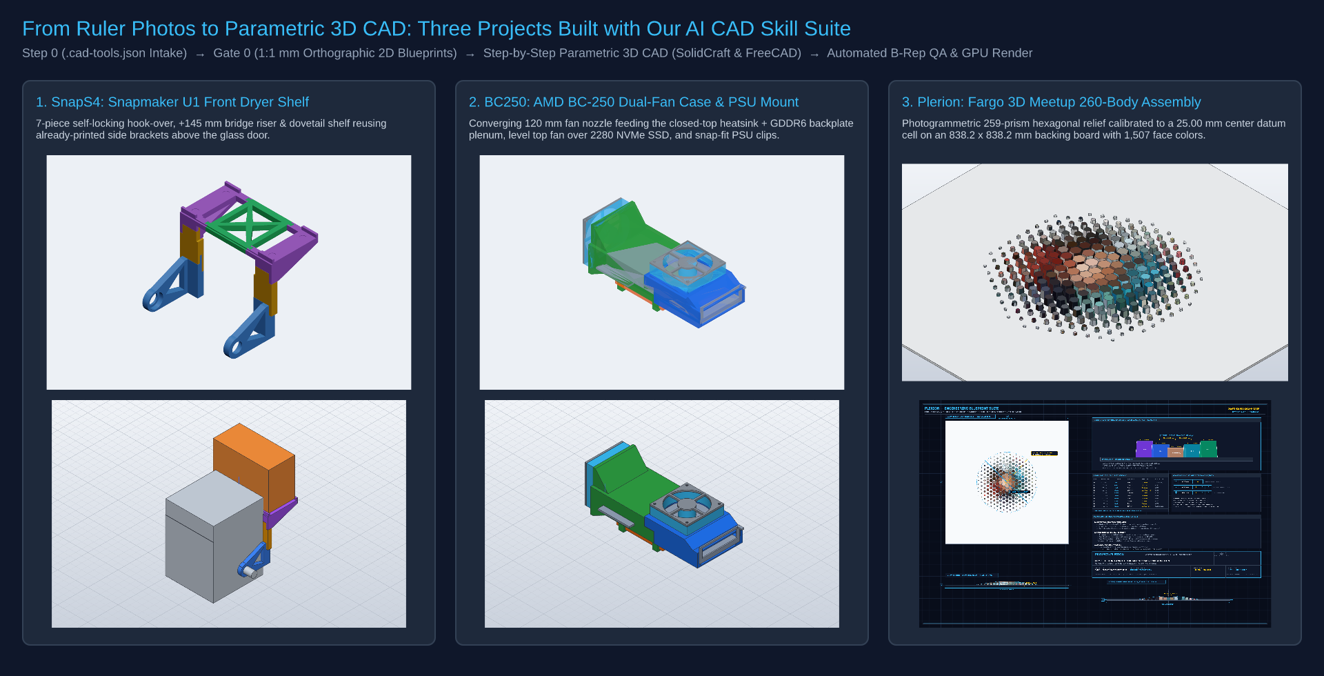
The philosophy: Design like a human, not a black-box mesh generator
Once that first switch bracket came off the printer, I started thinking about how a human actually designs a functional part. When you sit down to engineer a bracket or an enclosure, you do not just say, "Build this 3D object," and hope the final shape fits. You start with measurements and a blueprint.
We built our AI CAD skill suite around two core decisions:
1. Blueprint first, 3D second
Instead of jumping straight from a prompt into 3D solids, we seed the project with source photos that have a steel ruler or combination square placed directly on the same plane as the feature we need to measure. Keeping the ruler coplanar with the mounting bosses or chassis edges minimizes camera perspective distortion and gives the QA skill a reliable millimeter reference right on the target surface. The agent then uses FigCraft and CADCraft to draft 1:1 millimeter orthographic 2D blueprints first, showing the Side, Front, and Top views on a millimeter grid.
Then it stops at Gate 0. As a human designer, I can sit there and review the 2D blueprint before a single 3D feature is extruded. Because smartphone lenses still introduce slight parallax toward the edges of a frame, Gate 0 acts as our metrological safety net. I can see every measurement the AI pulled from the photos, double-check those numbers against the physical device on my desk with calipers or a ruler, and hand any corrections back to the model in seconds.
2. Intentional step-by-step history as a teaching and editing tool
A lot of AI tools only care about spitting out a single final mesh or a collapsed solid at the end. If your only goal is saving tokens, having the AI dump one baked file at the end is cheaper.
We went the opposite direction on purpose. Our skills require the AI to build every single step in the CAD timeline:
- Define named user parameters for bore sizes, wall thicknesses, and clearance allowances.
- Put down a 2D sketch on a datum plane.
- Run the first extrude.
- Add each subsequent cut, bore, counterbore, dovetail, and fillet as its own named step in the tree.
We did this for two reasons. First, it turns every generated file into a teaching tool. When you open the final assembled piece in SolidCraft or FreeCAD, you can walk back through the entire history tree and see how every joint and feature was constructed.
Second, it makes the model adjustable without re-running the AI. If you print a part and discover your printer's inner-hole tolerance is 0.3 mm tight, you do not have to burn another AI prompt cycle and hope it keeps the rest of the part intact. You just open the .solidcraft or .FCStd file, change the parameter or sketch at that specific step, and export a fresh 3MF or STL.
For a seasoned CAD designer, this is built to accelerate workflows, not replace them. You can have the agent draft three or four base blueprints and parametric trees in parallel, getting each concept 90% of the way there so you can step in and fine-tune the final details.
Inside the four-skill pipeline
All four skills and custom agent definitions are included in our ./ai-cad-skill-pack/ folder so you can browse them directly or pull them into your own workspace:
svg-blueprint-drafter(agent) for 1:1 mm 2D orthographic drawings. Drafts Side, Front, and Top views at1 px = 1 mmscale in SVG, FigCraft, and CADCraft DXF, then pauses at Gate 0 for human inspection.cad-qa-inspector(agent) for metrology and clearance checks. Runs Step 0 intake, checks EXIF rotation on ruler photos, calibrates pixel-to-millimeter scale, verifies cross-view alignment, and runs B-rep interference checks.solidcraft-3d-builder(agent) for native parametric timelines and 3MF slicer packages. Drivessolidcraft-clistep by step usingparameters.add,sketch.create,solid.extrude, andsolid.cylinder, runs B-rep clearance audits, exports face-tagged 3MF files, and renders Vulkan GPU snapshots.freecad-step-builder(agent) for OpenCASCADE solids and WebGL viewers. Builds aParamsspreadsheet and separatePartDesign::Bodytrees in headless FreeCAD alongside a standalone HTML/WebGL assembly viewer.
How a project moves through the pipeline
Every build follows the same three-stage handoff:
- Step 0 Intake (
Source Images/+.cad-tools.json). You drop ruler photos intoSource Images/.cad-qa-inspectorverifies EXIF orientation, checks your printer's build volume in.cad-tools.json, and calibrates the pixel-to-millimeter scale along each ruler plane. - Gate 0 2D Blueprint Review (
svg-blueprint-drafter+cad-qa-inspector). The blueprint drafter generates 1:1 mm Side, Front, and Top orthographic views inDrafts/andWorking Drafts/. The pipeline pauses here so you can check critical dimensions against your physical hardware before any 3D modeling starts. - Gate 1 Parametric 3D Build (
solidcraft-3d-builderorfreecad-step-builder). Once you approve the 2D blueprint, the 3D builder constructs each part step by step in the feature tree, logs every operation inHistory/Steps.md, runs an automated zero-clash B-rep interference check, and exports ready-to-print.3mf,.step, and.stlfiles.
Translating everyday maker descriptions into mechanical features
As we worked through our projects, we also taught the skills to translate casual descriptions into formal mechanical engineering geometry:
| What we ask for in plain English | What the AI CAD skill actually models |
|---|---|
| "Put a reverse-L notch at the top back to clear the cover that hangs over by 5 mm" | Stepped edge rabbet relief, 6 mm x 5 mm, above a lower datum contact toe |
| "Make the round spool hole flush with the side arm so it prints flat on the bed" | Coplanar build-plate datum face at Z_print = 0 with zero out-of-plane boss stickout |
| "Wrap the bracket around the front corner so it cannot twist on the round peg" | 90-degree orthogonal anti-rotation return flange creating a two-point force couple |
| "Have the top rail hook straight down over the front leg" | Interlocking male cleat tang and shrouded female clevis saddle with axial capture cheeks |
| "Rest the middle piece on a lip with drop-in dovetails instead of loose bowties" | Shouldered half-lap bearing ledger with blind dovetail mortises and integral tenons |
| "Hold the power supply in place with clips and funnel a 120 mm fan into the heatsink" | Cantilever snap-fit overhang hooks with 45-degree lead-in chamfers and a converging bellmouth plenum |
Project 1: SnapS4 filament dryer shelf for the Snapmaker U1
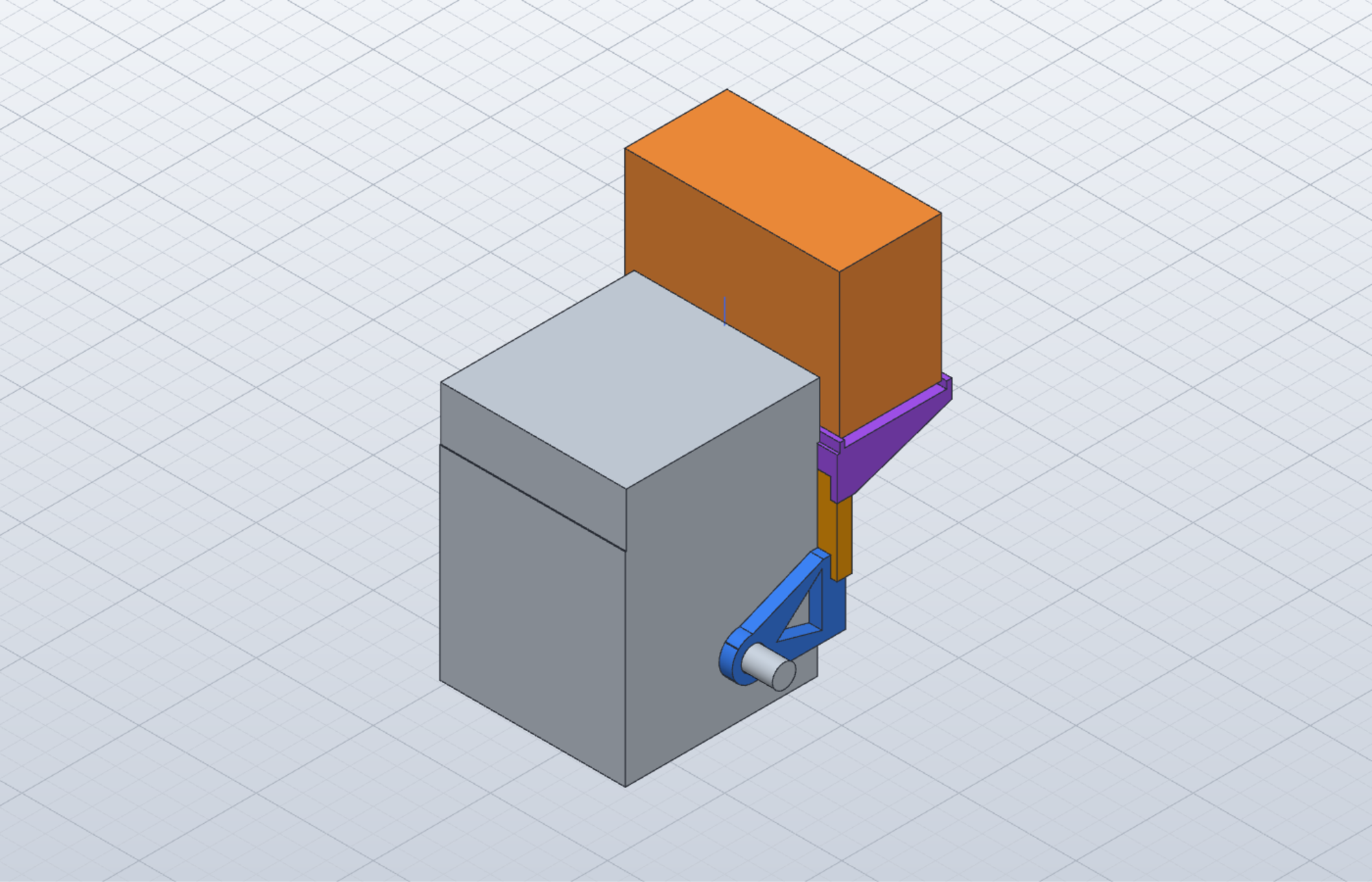
After the MikroTik switch fan holder, my next real-world problem was filament management on my Snapmaker U1. I wanted to move my Sunlu FilaDryer S4, which weighs 5.0 kg when loaded with four spools, up in front of the U1 so the filament feeds cleanly into the printer and the spools are right there at the front when I need to swap rolls. At the same time, I still needed full access to open the front glass door, see the touchscreen, and lift off the top acrylic cover.
Seeding the blueprint with steel ruler photos
To test whether we could pull reliable dimensions straight from photos, I held a 300 mm steel ruler and a combination square flat against the U1's side spool holder boss, the front glass door, and the front pillars, and took four reference photos.
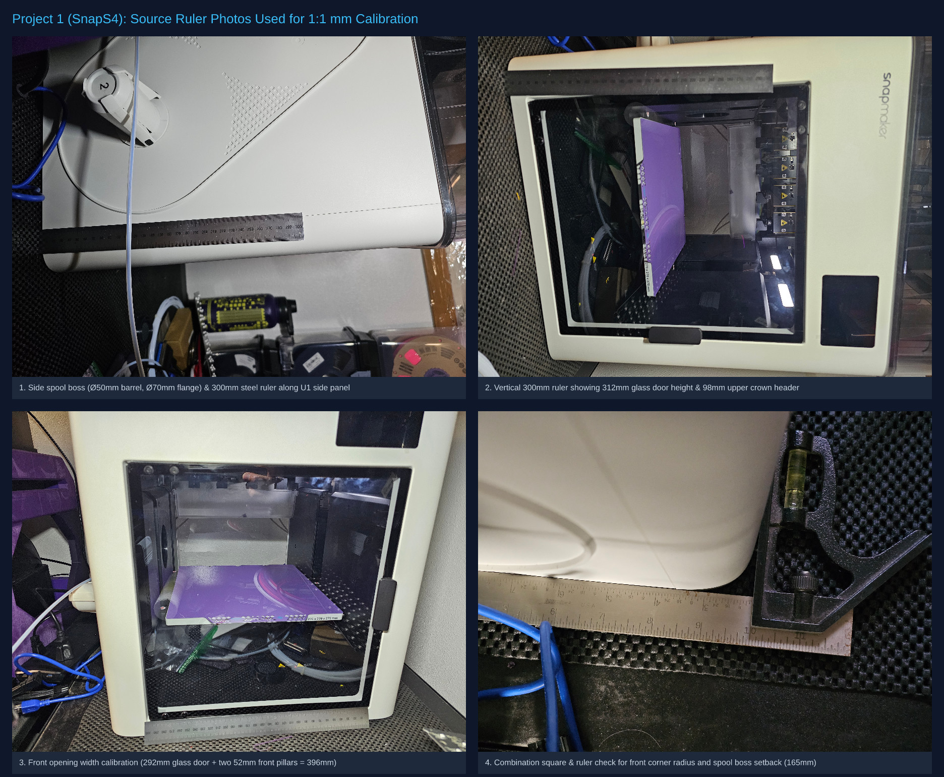
This first photo-calibrated project immediately proved why the Gate 0 2D blueprint review and QA checks matter. We had already printed the two lower side spool brackets, Part B-L and Part B-R, when we checked how the shelf height lined up with the door.
In the vertical ruler photos 20261017_102442.jpg and 20261017_102510.jpg, the 300 mm steel ruler stood on the bottom mat and ended at 300 mm, just below the top edge of the 312 mm glass door. Including the 98 mm upper crown header above the door, the full white chassis height was 435 mm. That meant the side spool holder center was 305 mm below the top crown at Z = -305 mm, not 160 mm.
If we hooked the top shelf rails directly onto our already-printed Part B-L and Part B-R brackets, the Sunlu S4 would sit 145 mm too low right across the glass door and touchscreen.
Saving 400g of already-printed filament with a +145 mm bridge riser
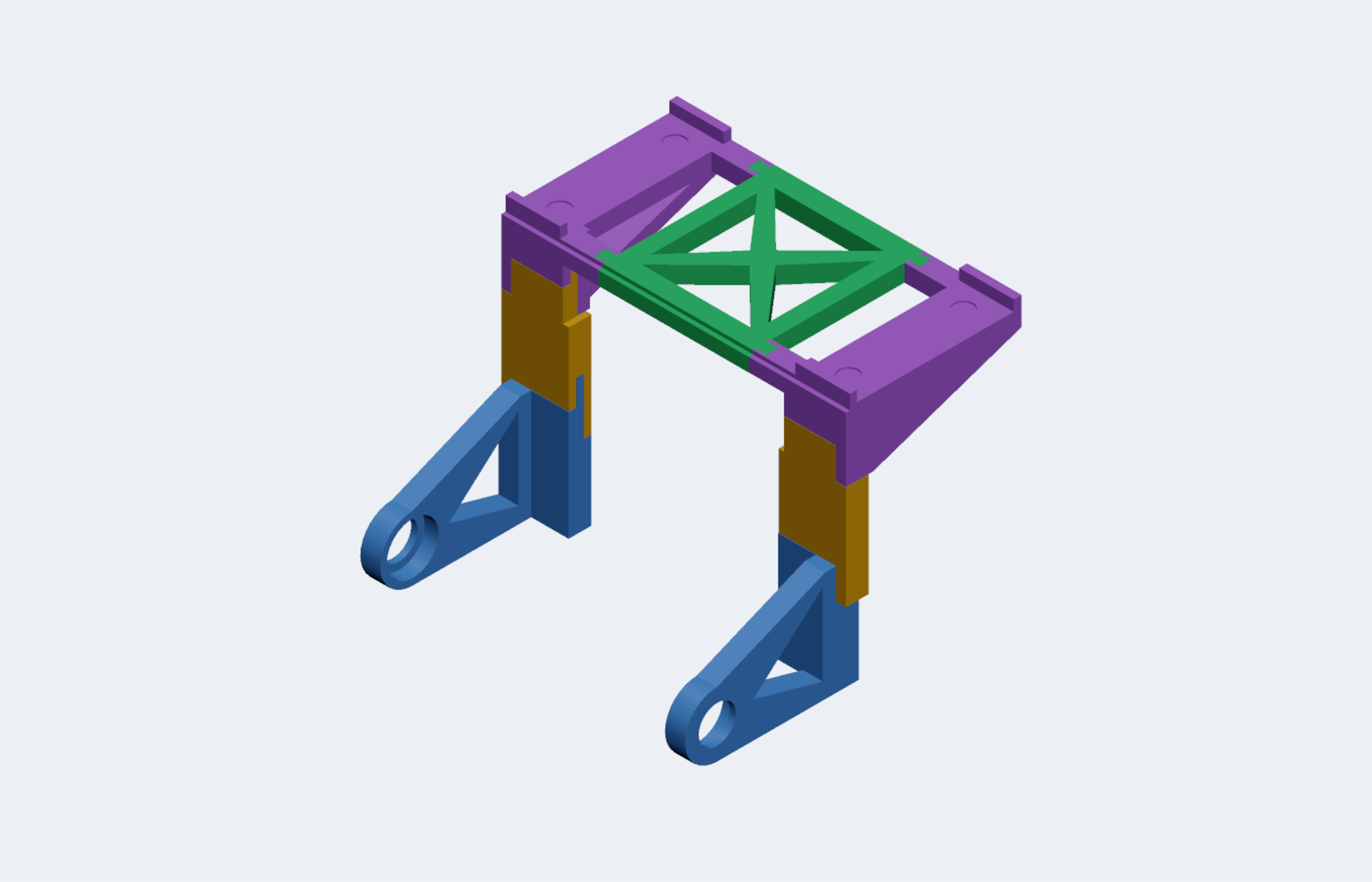
Because we had the 1:1 mm 2D blueprint in front of us, we did not have to throw away nearly 400 grams of already-printed filament on Part B-L and Part B-R. Instead, we updated the blueprint to add an intermediate vertical bridge riser, Part D-L and Part D-R, that climbs +145.0 mm up the 52 mm front pillars outside the glass door opening.
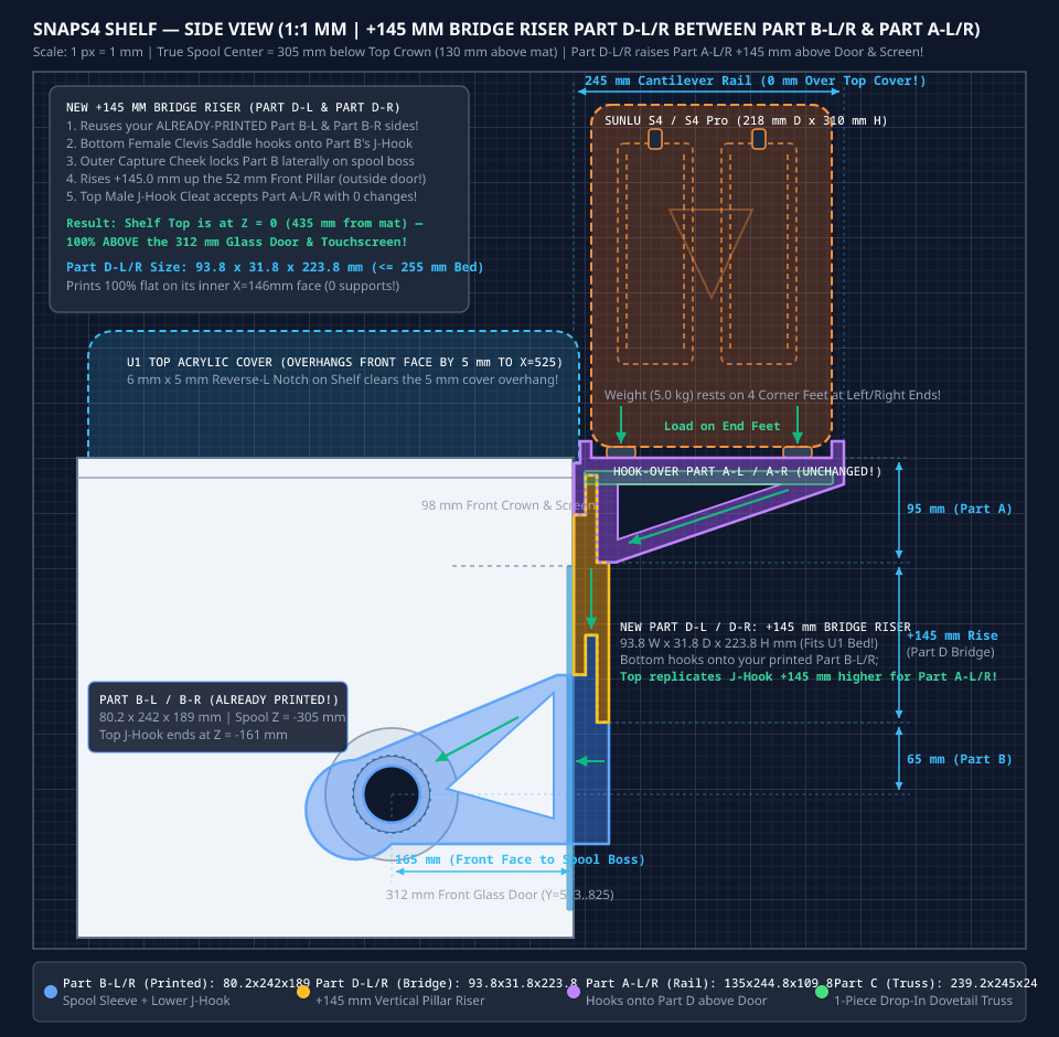
The bottom of Part D has a female J-hook clevis saddle and outer capture cheek that locks onto the existing Part B cleat. The top of Part D reproduces that exact same male J-hook cleat 145.0 mm higher up the pillar, with an 8.0 mm inner relief step to clear the touchscreen bezel. The upper cantilever rails, Part A-L and Part A-R, and the drop-in dovetail X-truss, Part C, hook onto Part D flush with the top crown at Z = 0.0 mm, clearing the 5 mm top cover overhang with a 6 x 5 mm rabbet notch.
SnapS4 assembly and hardware envelope
| Part / Component | Envelope (W x D x H) | Role & Mechanical Interface |
|---|---|---|
Part A-L & Part A-R (Upper Cantilever Rails) |
135.0 x 244.8 x 109.8 mm |
Support the outer bays of the Sunlu S4; hook over the top crown with a 6 x 5 mm rabbet relief notch and lock into the top of Part D |
Part B-L & Part B-R (Side Spool Anchors) |
80.2 x 242.0 x 189.0 mm |
Mount over the U1 side spool bosses (53.5 mm ID bore with 0.25 mm radial clearance) with a 90-degree front corner anti-rotation wrap |
Part C (Center Dovetail X-Truss) |
239.2 x 245.0 x 24.0 mm |
Bridges Part A-L and Part A-R across shouldered half-lap ledgers using four integral drop-in dovetail tenons (0.20 mm clearance) |
Part D-L & Part D-R (+145 mm Bridge Risers) |
93.8 x 31.8 x 223.8 mm |
Reuse the already-printed Part B brackets by translating the male J-hook interface +145.0 mm upward along the front pillars |
| Sunlu FilaDryer S4 (Supported Payload) | 458.0 x 218.0 x 310.0 mm |
5.0 kg four-spool filament dryer held clear of the 292.0 x 312.0 mm glass door and 80.0 x 63.0 mm touchscreen |
Project 2: AMD BC-250 dual-fan enclosure and PSU mount
With the photo-to-blueprint-to-CAD loop proven on SnapS4, we pointed the skill at a denser thermal and mechanical packaging problem: building a custom enclosure and power supply mount for an AMD BC-250 crypto-mining blade.
If you have seen the BC-250 pop up in homelab and budget gaming builds, you know why it needs custom 3D-printed ductwork. The board packs a cut-down PlayStation 5 APU with 16 GB of shared GDDR6 memory onto a bare server blade with a massive passive aluminum fin-stack heatsink, zero onboard fans, and exposed backside memory chips. To turn it into a quiet desktop machine, we needed to channel two high-static-pressure 120 mm Arctic P12 Pro PST fans through the heatsink and across the rear M.2 NVMe slot while clipping an FSP 500W Flex-ATX power supply underneath.
Iterating on three blueprint options before touching 3D CAD
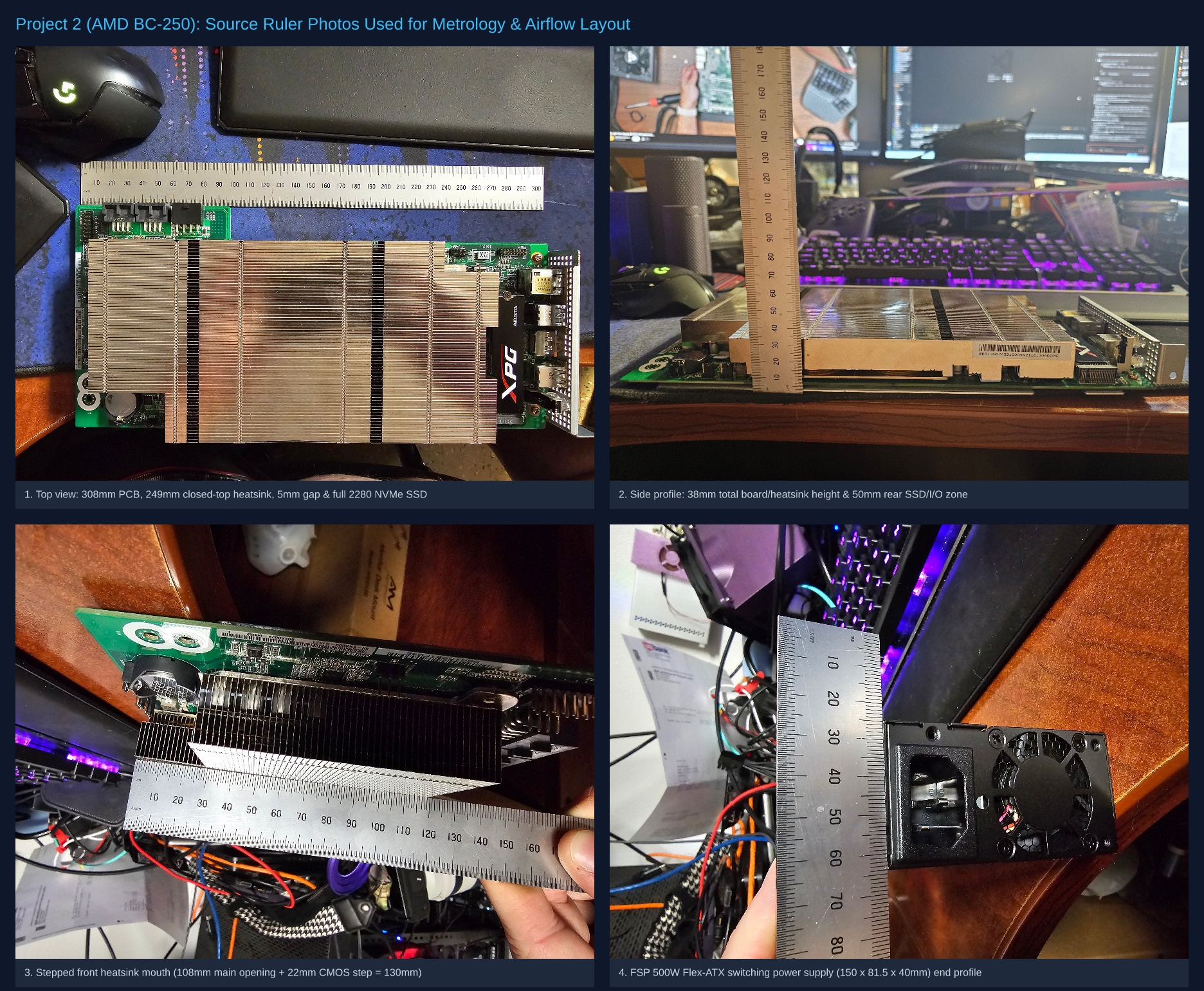
We took coplanar ruler photos of the BC-250 PCB, the stepped front heatsink mouth, the rear M.2 2280 NVMe SSD slot, and the Flex-ATX power supply, and dropped the Arctic P12 Pro PST fan spec sheet into Source Images/.
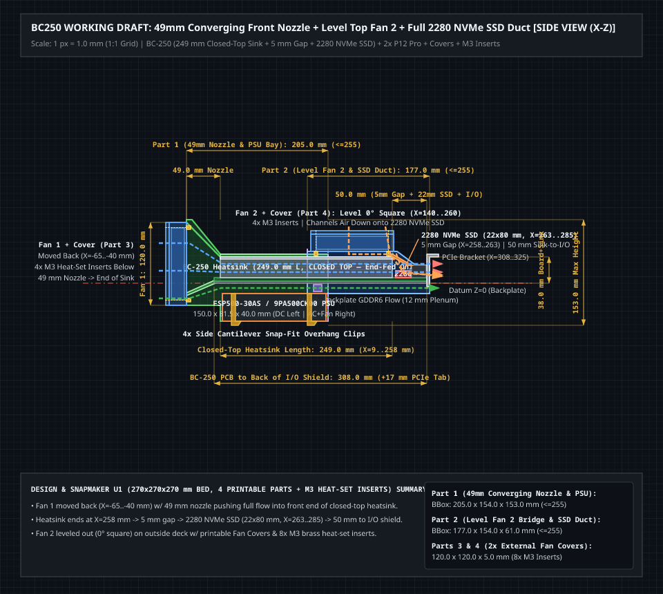
Instead of guessing at one layout, the blueprint skill drafted three candidate concepts inside a Drafts/ folder: Option 1: Wind Tunnel, Option 2: Sandwich, and Option 3: Dual Plenum. We picked Option 1 and moved it into Working Drafts/ where we could inspect the measurements and refine the airflow path in 2D:
- End-feeding the closed-top heatsink. Looking closely at the hardware, the top of the
249.0 mmlong passive fin heatsink is sealed with folded zipper fins, so all cooling air must enter through the front mouth. We pulledFan 149.0 mmforward and shapedPart 1into a converging bellmouth nozzle that pushes 88% of the 120 mm fan's flow straight into the stepped130.0 mmfront fin opening while bleeding 12% underneath into a12.0 mmplenum across the backside GDDR6 memory. - Double-checking the 2280 NVMe SSD position. Ruler photo
20261018_090018.jpgshowed a5.0 mmgap behind the heatsink atX = 258.0 to 263.0 mm, followed by a full22.0 x 80.0 mmM.2 2280 NVMe SSD sitting crosswise in the50.0 mmrear zone ahead of the I/O shield atX = 308.0 mm. - Leveling Fan 2 for flat printing. An early blueprint tilted the second 120 mm fan at 10 degrees, which would have printed with rough stair-stepping. In the 2D side view, we leveled
Fan 2to 0 degrees square on top ofPart 2, bridging the front and rear enclosure halves across a30.0 mmhalf-lap joint with a0.20 mmslip-fit tolerance and routing air down a 45-degree hood over the 2280 NVMe SSD. - Adding printable fan guards, M3 heat-set inserts, and PSU snap-fit clips. We placed both fans on the outside of the case with printable blade guards,
Part 3andPart 4, anchored into eight M3 brass heat-set inserts (4.0 mmbores), and added four cantilever snap-fit overhang clips with a0.25 mmclearance allowance underneathPart 1to hold the 500W Flex-ATX power supply.
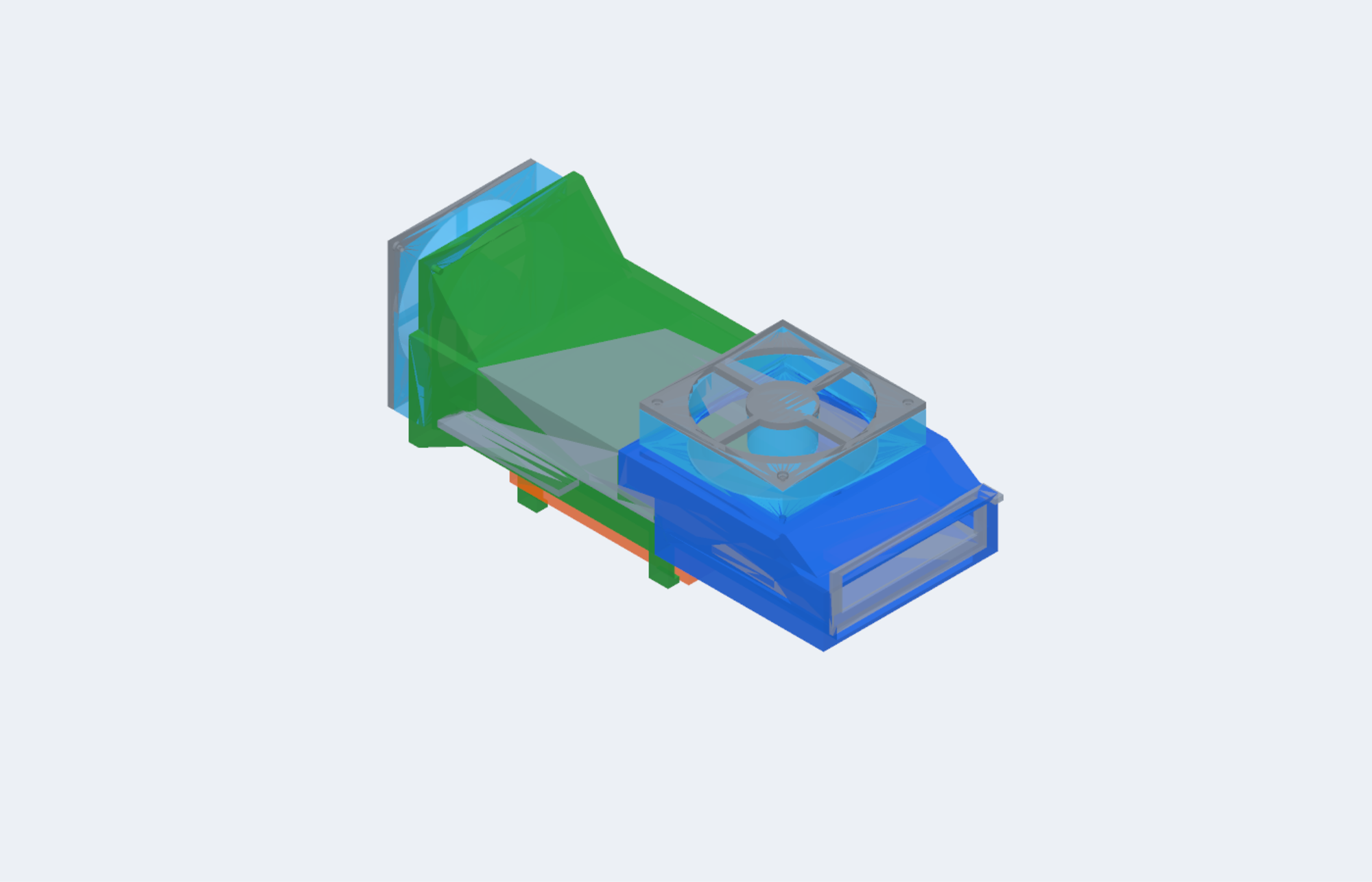
BC-250 printable parts and hardware envelope
| Part / Component | Envelope (L x W x H) | Role & Key Clearances |
|---|---|---|
Part 1 (Front Intake Bellmouth & PSU Cradle) |
204.0 x 135.0 x 165.0 mm |
Funnels Fan 1 into the closed-top heatsink (88%) and lower GDDR6 plenum (12%); cradles the Flex-ATX PSU underneath via four snap-fit clips |
Part 2 (Rear Exhaust & NVMe Cooling Hood) |
191.0 x 135.0 x 165.0 mm |
Interlocks with Part 1 across a 30.0 mm half-lap joint (0.20 mm clearance); mounts Fan 2 flat at 0 degrees and ducts air over the rear M.2 2280 SSD |
Part 3 & Part 4 (120 mm Hex Fan Guards) |
120.0 x 120.0 x 5.0 mm |
External finger guards on standard 105.0 x 105.0 mm hole centers fastened into eight M3 x 5.7 mm brass heat-set inserts (4.0 mm mounting bores) |
| AMD BC-250 Server Blade (Hardware Reference) | 308.0 x 121.0 x 66.0 mm |
Bare PS5 APU compute board with 249.0 mm closed-top zipper-fin heatsink and rear crosswise M.2 2280 NVMe socket |
| FSP 500W Flex-ATX PSU & 2x Arctic P12 Pro PST | 150.0 x 81.5 x 40.0 mm (PSU) |
Switching power supply retained below Part 1 (0.25 mm clip clearance) and two 120.0 x 120.0 x 25.0 mm high-static-pressure fans |
Because we caught all four design changes in the 2D blueprint stage, the very first SolidCraft 3D build pass generated all four printable parts and the 9-body hardware assembly cleanly in 78 step-by-step timeline operations with zero B-rep interferences.
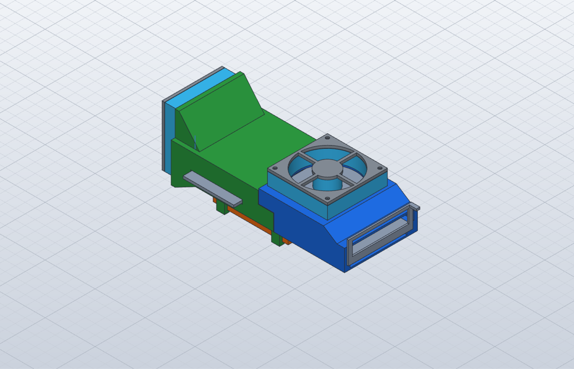
Project 3: Plerion 260-body reconstruction from the October special session
Our third project came directly out of the October Fargo 3D Printing Meetup Special Session on building CAD with AI, and it served as a scale and complexity stress test for our parametric pipeline. While SnapS4 and BC250 focused on multi-part mechanical brackets and airflow ducts, we wanted to see what happens when the same photo-to-blueprint-to-SolidCraft workflow is asked to reconstruct hundreds of individual geometric bodies in a single parametric timeline.
Before the meeting, we asked community members to bring in objects or photos they wanted to run through the AI CAD pipeline live. One of our members brought in 9 photos they had taken of a piece they thought would make a great LED-backlit wall display. That kicked off our third build and became the model for our November community print challenge.
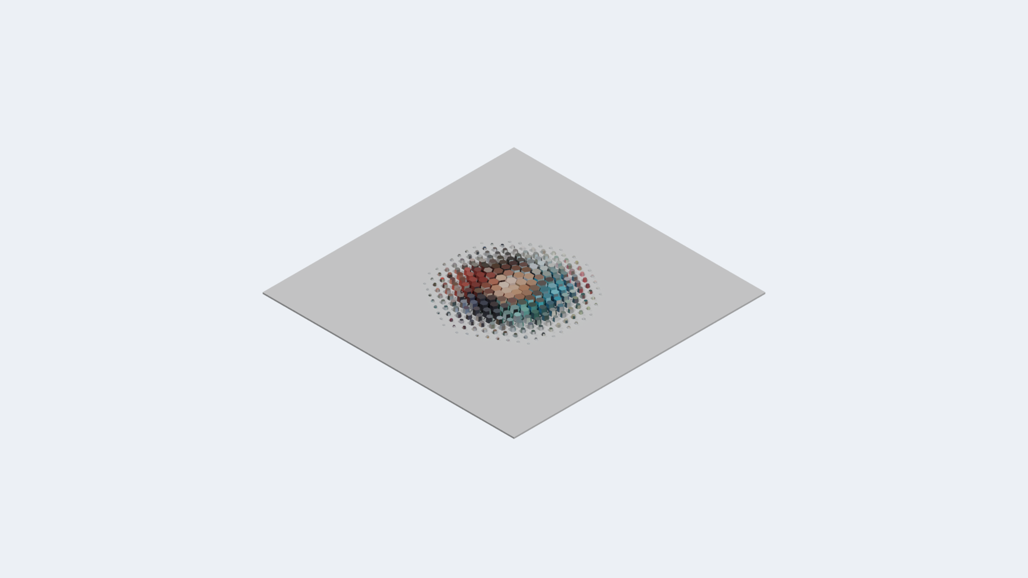
The piece in the photos is Plerion, a 33 x 33 inch, or 838.2 x 838.2 mm, mixed-media relief sculpture composed of 259 hexagonal prisms arranged in concentric rings, each with its own height, axial rotation, and color palette.
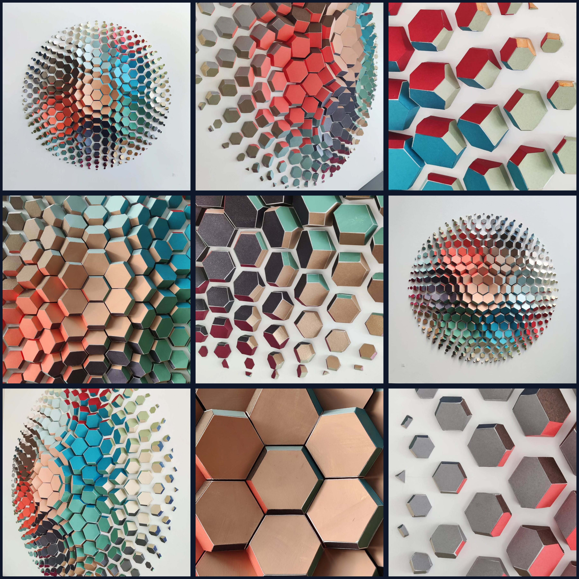
Calibrating 259 hexagonal prisms in FigCraft and SolidCraft
Using the reference photos, we calibrated the lattice to the center datum hexagon at Ring 0, q = 0, r = 0, with a 25.000 mm flat-to-flat height, a 28.868 mm corner-to-corner width, and a 14.434 mm side length. That set the photogrammetric scale at 0.430849 mm/px across the 411.89 mm diameter array of 259 prisms on the 838.2 x 838.2 x 5.0 mm backing board.
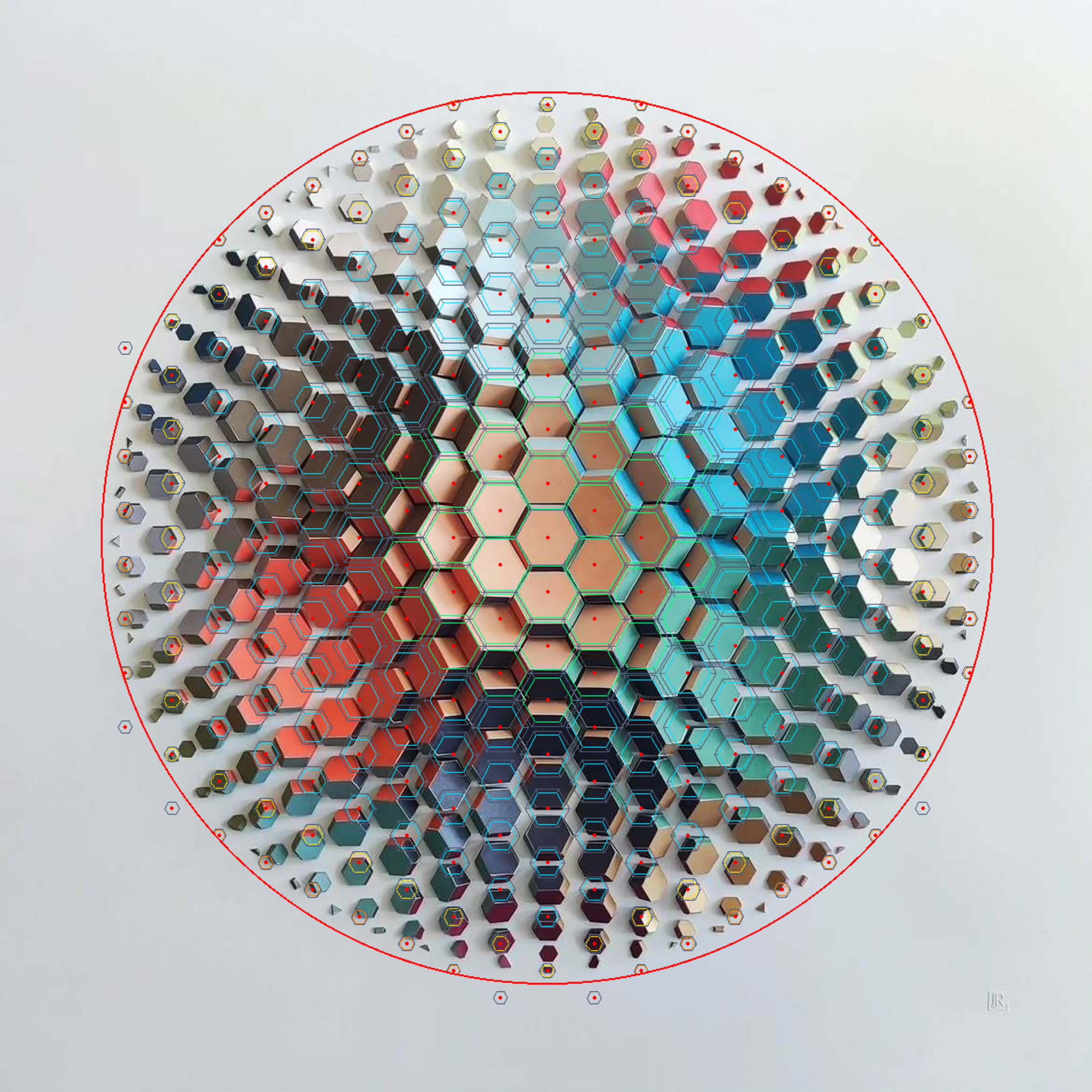
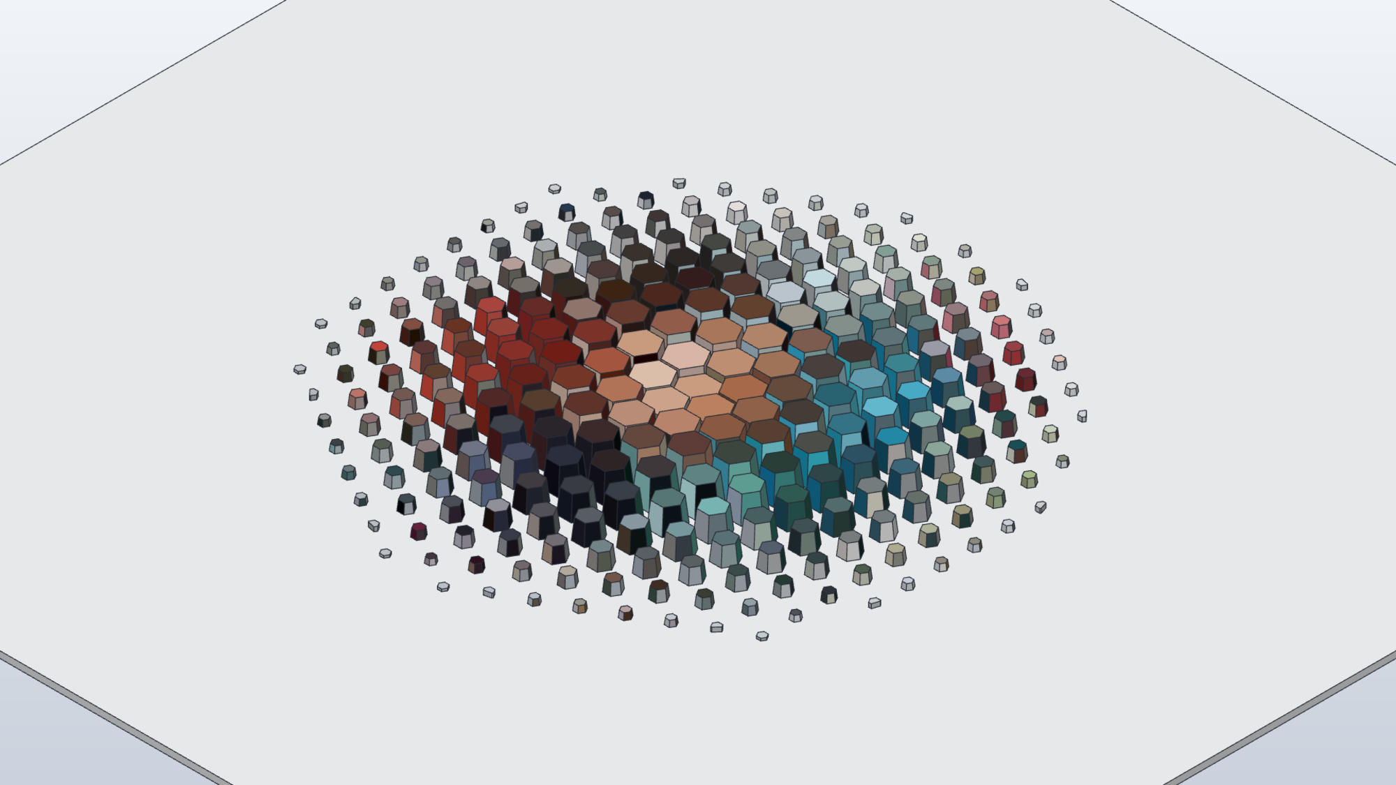
We then used FigCraft and CADCraft to compile a 1:1 mm third-angle orthographic master blueprint sheet across Plerion_Blueprints.figcraft, Plerion_Master_Sheet.svg, Plerion_Blueprints.pdf, and AutoCAD .dxf files. It shows the top plan view, front and side elevations, a 5:1 cross-sectional detail of the central caldera dish starting at 12.50 mm in the center, rising to a 24.00 mm peak ridge at Ring 3, and tapering to 3.00 mm at Ring 9, plus the radial decay table.
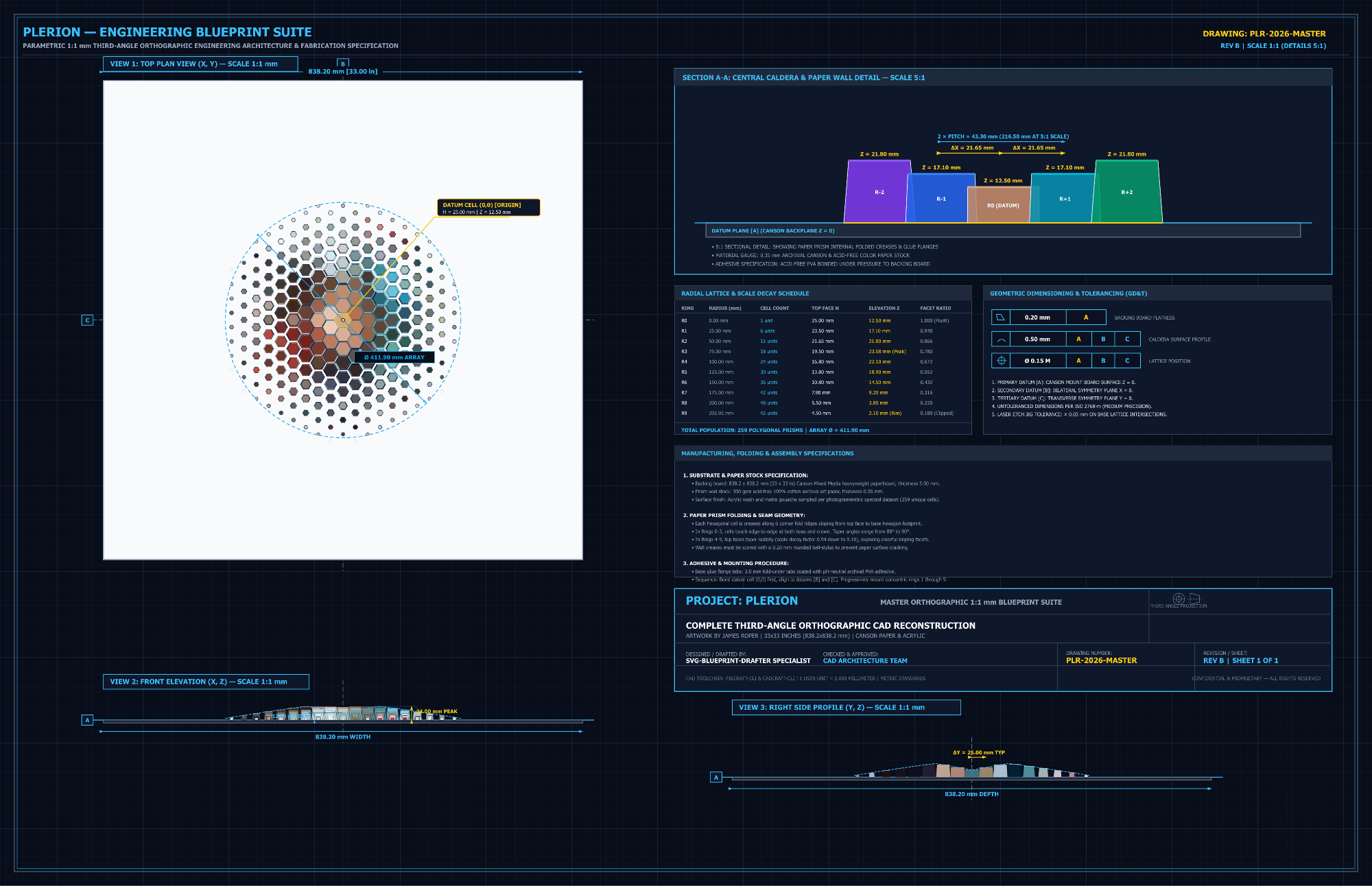
From that approved blueprint dataset, SolidCraft executed a 2,831-step parametric script, Plerion_Assembly_Script.json, to construct all 260 closed B-rep solid bodies with 2,078 planar faces and 4,674 edges, and assign 1,507 per-face PBR color appearances sampled from the source photographs.
The closeup isometric render below shows the stepped 3D hexagonal prism heights across the central caldera and peak ring, followed by the full 838.2 x 838.2 mm board render:
How the skill evolved across all four builds
| Build stage | What we built | What it taught us to add to the AI CAD skill |
|---|---|---|
| 0. Origin: MikroTik Switch Fan | Clip-on 40 mm Noctua fan holder over SFP+ cages on a MikroTik 5-port 10G switch | Proved AI could replace zip ties with a quick functional bracket in FreeCAD, and motivated moving to the MCP-powered Craft apps: FigCraft, CADCraft, and SolidCraft. |
1. SnapU1S4: SnapS4 Shelf |
7-piece front filament dryer shelf for the Sunlu S4 on the Snapmaker U1 | Added coplanar steel-ruler photo calibration, EXIF orientation checks, the mandatory Gate 0 2D Blueprint review, and zero-waste bridge risers in Part D to reuse already-printed parts. |
2. BC250: AMD BC-250 Case |
Dual-120 mm fan converging airflow shroud and snap-fit 500W Flex-ATX PSU mount | Added multi-option Drafts/ vs. Working Drafts/ blueprint folders, chronological History/Steps.md logs, and step-by-step parametric trees for easy tolerance tweaking. |
3. Plerion: October Meetup Session |
260-body parametric relief assembly for an LED-backlit wall piece from 9 member photos | Stress-tested the pipeline at scale by reconstructing 259 hexagonal prisms with 1,507 per-face colors, multi-page FigCraft and DXF master blueprint sheets, and a 2,831-step SolidCraft script. |
How to do this yourself
We packaged all of the skills, custom agents, and workspace steering files into ./ai-cad-skill-pack/ so you can run this exact workflow on your own projects.
This skill pack was originally created and tested with Gemini, but Claude or any other modern coding and reasoning model can adapt these steps easily. We included AGENTS.md, GEMINI.md, and CLAUDE.md in the root of the package so your preferred AI assistant picks up the routing table and blueprint-first rules right away.
Step 1: Download the ZIP package or pull the folder with Git
Choose whichever method fits your setup:
Option A: Download the packaged ZIP archive directly
- One-click download:
ai-cad-skill-pack.zip - Extract the downloaded archive into your project workspace:
unzip ai-cad-skill-pack.zip -d my-cad-workspace
cd my-cad-workspace
- One-click download:
Option B: Clone only the skill pack folder with Git sparse-checkout
- If you want to pull just
Articles/ai-cad-skill-packvia Git without downloading the rest of the meetup repository:git clone --filter=blob:none --no-checkout https://meetup.fargo3d.com/Fargo3d/3DPrintMeetup.git my-cad-workspace cd my-cad-workspace git sparse-checkout init --cone git sparse-checkout set Articles/ai-cad-skill-pack git checkout master - Then copy the skill, agent, and steering files into your workspace root:
cp -r Articles/ai-cad-skill-pack/.agents Articles/ai-cad-skill-pack/.github Articles/ai-cad-skill-pack/AGENTS.md Articles/ai-cad-skill-pack/GEMINI.md Articles/ai-cad-skill-pack/CLAUDE.md .
cp Articles/ai-cad-skill-pack/.cad-tools.example.json .cad-tools.json
- If you want to pull just
Step 2: Install the Craft & CAD tools and configure .cad-tools.json
You can install FigCraft and CADCraft in one click using the ArtCraft Launcher, grab SolidCraft from its GitHub releases, or build any of the tools from source:
| Tool | Role in the AI CAD Pipeline | Repository | Releases & Downloads |
|---|---|---|---|
| ArtCraft Launcher | One-click installer and updater for the Craft App Suite (FigCraft, CADCraft, and more) |
storytold/craft-launcher |
Latest Release |
| FigCraft | 1:1 mm 2D vector blueprints, multi-view blueprint boards (.figcraft), SVG/PDF/PNG exports, and figcraft-cli mcp server. Uses storytold/craft-fonts when building from source |
storytold/figcraft |
Latest Release |
| CADCraft | Precision 1:1 mm 2D CAD drafting, native .dxf/.dwg generation, and cadcraft-cli mcp server |
storytold/cadcraft |
Latest Release |
| SolidCraft | Parametric 3D CAD solid modeler with editable feature timeline, B-rep clearance audits, 3MF export, Vulkan GPU rendering, and solidcraft-cli mcp server |
tangency-labs/solidcraft |
Latest Release | solidcraft.io |
| FreeCAD | Optional headless OpenCASCADE (FreeCADCmd) parametric PartDesign::Body + Spreadsheet builder for .FCStd, .step, and .stl exports |
FreeCAD/FreeCAD |
freecad.org |
Once installed, copy .cad-tools.example.json to .cad-tools.json in your workspace root and set the paths to whichever CAD tools you have installed (solidcraft-cli, cadcraft-cli, figcraft-cli, or headless FreeCAD via FreeCADCmd), along with your printer's build volume. If you skip this step, the agent will ask you for your tool paths and printer size on its first run and create .cad-tools.json for you.
Step 3: Add reference photos with a ruler and start at Gate 0
- Create a folder for your project such as
MyProject/Source Images/and drop in photos of your hardware or object with a steel ruler held flat on the same plane as the mounting features. - Open your workspace in your AI coding tool using Gemini, Claude, or another model and give it a clear Gate 0 kickoff prompt like this:
Follow AGENTS.md. Inspect the ruler photos in MyProject/Source Images/ with cad-qa-inspector to verify EXIF orientation and calibrate the millimeter scale. Then use svg-blueprint-drafter to draft 1:1 mm Side, Front, and Top 2D orthographic blueprints for [describe your bracket or enclosure] in MyProject/Drafts/ and stop at Gate 0 so I can verify the measurements before any 3D CAD begins.
- Review the generated 1:1 mm Side, Front, and Top 2D blueprints against your physical part with a ruler or calipers.
- Once the 2D blueprint measurements look right, tell the agent to proceed to Gate 1 and build the step-by-step parametric 3D assembly in SolidCraft or FreeCAD.
Browse the packaged files directly in the repo
- Pack overview & instructions:
./ai-cad-skill-pack/readme.md - Direct ZIP package:
ai-cad-skill-pack.zip - Workspace steering & configuration:
AGENTS.md|GEMINI.md|CLAUDE.md|.cad-tools.example.json - Skills (
.agents/skills/): - Custom agents (
.github/agents/):
Community shoutout & how to get involved
This AI CAD skill suite is a living project that we are continuing to refine and share with the Fargo 3D community.
A huge shoutout to 3D Fuel, who provided our original meeting space, helped start the community we have today in Fargo 3D, and continues to be a great partner and sponsor by hosting events, promoting our monthly challenges, and bringing local makers together. Remember you can always support them and save on filament with code FARGO3D on 3DFuel.com.
Join us at a meetup & share feedback
- Join us at a monthly meetup. You are always welcome to join us in person at the West Fargo Public Library or hang out in the Fargo 3D Discord. Check our community events calendar and active monthly challenge for the next meeting date and theme.
- Open an issue or suggest improvements. If you have questions, run into an edge case, or want to see new capabilities added to the CAD skills, open an issue on our repository or drop a note in Discord so we can keep making these tools more reliable for everyone.
Last Updated: November 1, 2026